In this tutorial, I will introduce you to the concept of isometric content creation and the basics of designing with it, using the open source library As3isolib. We will use these skills to create a simple level editor, suitable for an isometric game.
Final Result Preview
Let's take a look at the final result we will be working towards:
The SWF has been squashed slightly to fit in the page; click here to see it full-size.
Step 1: What is Meant by "Isometric"
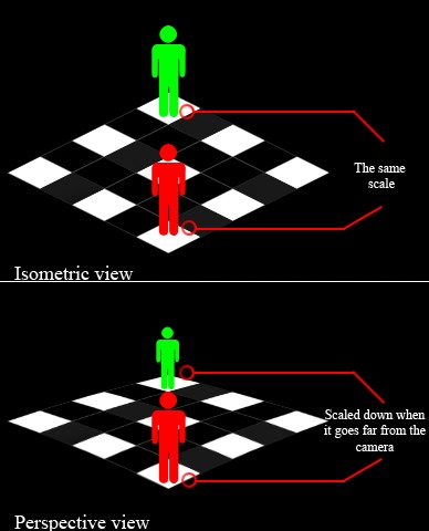
First, it's important to know what we mean by isometric. Isometric is a Greek term which means having equal measurement: all measurements are to scale, no matter how far close or how far in the distance they are from the viewpoint. So in mathematics, isometric projection is a type of projection which preserves distance along objects.
Suppose you are in an isometric view; you will have a 3D view (e.g. when a camera takes a photo of you) where no matter you are, you will be shown at the same scale according to that camera. This is in contrast to a true perspective, where you will be reduced in size when you are far away from the camera.
As3isolib handles all the underlying math involved in creating your scenes and views, so don't worry about the math!
Step 2: What Does Tile-Based Mean?
Tile based is a term used for any graphical content that uses tiles as a fundmental element. The concept itself is a bit old -- it was used in older games for technical reasons -- but this doesn't mean that tile based games are now dead; these days 3D rendering is, but these 3D games can be tile based (and many are). This is where isometric games come in. Tiles are usually rectangular, but there are also square tiles, triangular tiles and even hexagonal tiles (as in some Civilization titles).
Step 3: Rectangular Maps vs. Isometric Maps
Rectangular tiles are the easiest of all to work with, though most of the time, when working in rectangle land, you use square tiles. You can use other sizes, of course, but square seems to be a favorite. The point of view for games with square tiles is usually top down or overhead. This just means that all your graphics must be drawn as though you are looking down on the object. Sometimes you can give your game a slightly angled view so that you are looking mostly down, but you can see some of the front or back.
Another point of view for square tiles is the "side-scroller" view, where you are looking at the world from its side. This was very popular among older action games like Super Mario Bros and the original 2D Duke Nukem. In a rectangular map, moving along the X-axis means moving east, and moving along the Y-axis means moving south. In an isometric tilemap, depending on its type, moving along the X-axis might mean moving southeast, and moving along the Y-axis might mean moving southwest. In isometric tiles we still use rectangular areas to contain the tiles; this is not going to change. What will change is how you will render them.
(Editor's note: a great guide to different types of perspective can be found here.)
Step 4: Isometric Map Types
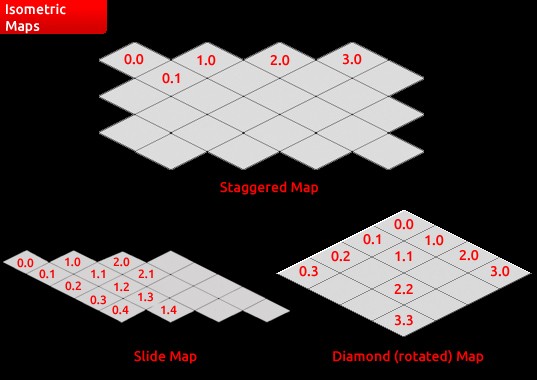
There are three types of isometric tilemaps: slide, staggered, and diamond. Each has its own set of quirks, its own methods of rendering, its own way of representing a tilemap, and its own method of navigating them. I will introduce them briefly in this step.
Slide Maps: The slide tilemap is probably the easiest to render, navigate, and interact with. Unfortunately, it has limited uses. It’s mainly used to scroll action games. Usually, a slide map has a horizontal X axis and a diagonal Y axis, although it is possible to have a vertical Y axis and a diagonal X axis. The tiles are blitted in horizontal rows top to bottom.
Staggered Maps: Staggered maps works perfectly in turn-based strategy games. It is also very useful in simulating a round world; it is best suited for maps that wrap around (move from one edge to the other). Each new row of the map is alternately shifted one-half of a tile left or right, which results in a zigzag pattern of tiles. The X axis is usually horizontal (increasing to the east), and the Y axis is southeast and southwest. Staggered maps are the most irregular of the three. The tiles are blitted in horizontal rows, top to bottom.
Diamond Maps: This type of map is very popular in real-time strategy games. These maps are the least offensive; slide maps have "tattered" tops and bottoms, and staggered maps have "tattered" edges, so diamond maps are the smoothest. In diamond maps, the only requirement is that both the X- and Y-axis are diagonal, so you can increase X-axis or Y-axis as fits you, like the X axis increasing to the southwest and the Y axis to the southeast.
Time to Code
That's enough context -- time to start developing!
Step 5: Downloading As3isolib
The first step is to download As3isolib (ActionScript 3 Isometric Library) which is an open source library for creating isometric projected content. One example of a game created using it is Empires and Allies from Zynga.
The library contains some assets like primitive shapes (rectangles, cubes, and so on) and some utilities to facilitate the creation of your isometric content. It is also free and can be used in any commercial work (though you can donate to it if you want).
Let's now download it from here. After downloading it uncompress the zip file to a new folder and name it Level Editor.
At any time while using As3isolib you can refer to its documentation through this link
Step 6: Setting Up the Scene
Fire up Flash and create a new ActionScript 3.0 FLA. Now we need to import the PSD file for the Level Editor interface which I have created (it's in the tutorial source files), or you can redesign the interface to what you feel looks good. So click on File>Import>Import To Stage, select the PSD file, and mark the "set stage size to same size as Photoshop canvas" option.
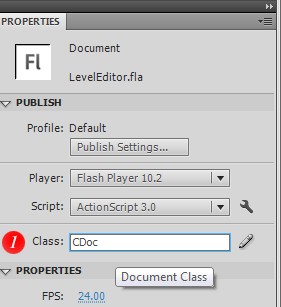
Now we have the raw images for our Level Editor. We need to create our Document Class in which we will implement our Level Editor: in the Properties panel in the Publish section you will find a Class field; write CDoc and click on the pencil button. Now save the ActionScript file which appears and name it CDoc.
Step 7: Making the Buttons
Lets make our three buttons in the bottom panel; right click on the button background image and select Convert to Symbol like what you see in the image, then rename the button to btnClear, insert text in the Up, Over, Down and Hit frames, and type into it CLEAR ALL. In the Over and Hit states insert the Hover image just like in the screenshot.
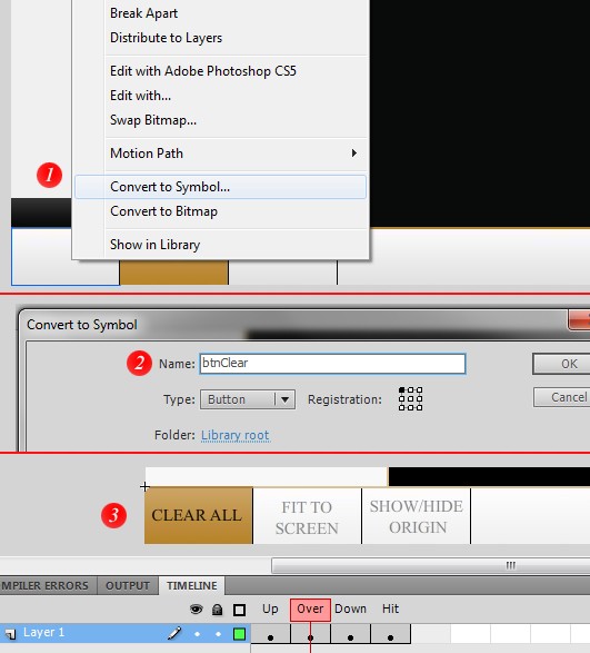
Then repeat this step to make the remaining two buttons.
Step 8: Creating the Tabs
Now we will create the three tabs: one of them will be for Soild Colors, another for Bricks, and the last one for Grass.
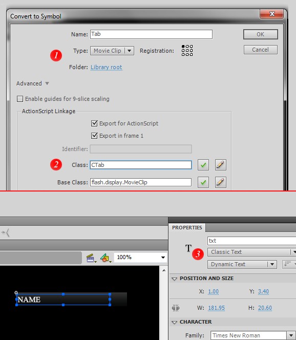
Draw a black gradient rectangle, right-click on it, and choose Convert to Symbol, then name it to Tab and choose its type to be a Movie Clip. Now mark the Export for ActionScript option, then in the Class field write CTab which will the class name for this Tab Movie Clip.
Double click on the Tab Movie Clip and insert text in it; inside this, write NAME. This text will be changed with the name of the tab; to allow this, convert this text to Dynamic Text with the name txt, just like in the image below.
Step 9: Implementing Our Tabs
Now we have a Movie Clip for our tab, we need to instantiate three copies of it and name them, so let's do that in our Document Class.
package
{
	import flash.events.MouseEvent;
	import flash.text.TextField;
	import flash.display.MovieClip;

	public class CTab extends MovieClip
	{
		public var txt:TextField;

		public function CTab(Name:String)
		{
			txt = this.txt as TextField;
			txt.text = Name;
			addEventListener(MouseEvent.ROLL_OVER, onRollOver, false, 0, true);
			addEventListener(MouseEvent.ROLL_OUT, onRollOut, false, 0, true);
		}

		protected function onRollOver(e:MouseEvent):void
		{
			this.alpha = 0.9;
		}

		protected function onRollOut(e:MouseEvent):void
		{
			this.alpha = 1;
		}
	}
}
package
{
	import flash.display.MovieClip;
	import flash.events.Event;
	import flash.events.MouseEvent;

	public class CDoc extends MovieClip
	{
		// Instantiating The Tabs
		private var Solid:CTab;
		private var Bricks:CTab;
		private var Grass:CTab;

		public function CDoc()
		{
			addEventListener(Event.ADDED_TO_STAGE, onAddedToStage, false, 0, true);
		}

		protected function onAddedToStage(e:Event):void
		{
			// Creating the tabs
			Solid = new CTab("SOLID");
			Solid.y = 469;
			Solid.addEventListener(MouseEvent.CLICK, onSolidClick, false, 0, true);
			addChild(Solid);

			Bricks = new CTab("BRICKS");
			Bricks.y = 494;
			Bricks.addEventListener(MouseEvent.CLICK, onBricksClick, false, 0, true);
			addChild(Bricks);

			Grass = new CTab("GRASS");
			Grass.y = 521;
			Grass.addEventListener(MouseEvent.CLICK, onGrassClick, false, 0, true);
			addChild(Grass);
		}

		protected function onSolidClick(e:MouseEvent):void
		{
			// will be implemented later
		}

		protected function onBricksClick(e:MouseEvent):void
		{
			// will be implemented later
		}

		protected function onGrassClick(e:MouseEvent):void
		{
			// will be implemented later
		}
	}
}
Step 10: Creating the Isometric View
Now let's learn about one of the most important things in As3isolib: the isometric view which serves like a camera that shows the isometric objects. It has a lot of helpful functions, like panning and zooming and focusing on a point or any object. It also provides the capability to hide/clip objects outside its boundaries and also lets us change its background and foreground content.
We will create two views in our Levels Editor, the first one is for our viewport which will have a grid in it and also the objects of our level, the other view is for the Objects Browser that will have a lot of object types that can be used in designing the level.
Now we will add the following code in our CDoc class -- be sure to check the line numbering, or just take a look at the source files of the tutorial.
//Add this line before the constructor
private var viewPort:IsoView;
viewPort = new IsoView();
viewPort.setSize(800, 600);
viewPort.centerOnPt(new Pt(-100, 100, 0), false);
addChildAt(viewPort, 0);
viewPort.addEventListener(MouseEvent.MOUSE_DOWN, onStartPan, false, 0, true);
viewPort.addEventListener(MouseEvent.MOUSE_WHEEL, onZoom, false, 0, true);
In the first line we created our IsoView and named it viewPort then in the second line we set its size to 800x600px. We need to center it on a point or on an object, so we created a new point from the built in as3isolib.geom package and gave it some x and y values in 3D isometric space (which we will discuss in the next step).
Now we need to show our viewPort so we added it to the display list of the document as a child, and to make it in the bottom of our interface to make sure it will not overlap with any other element we added it at index 0. Then we added two event listeners on our viewPort, one for panning and the other for zooming (which again I will explain later).
Step 11: Cartesian vs. Isometric Space
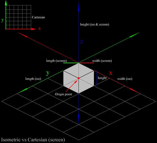
The coordinate system used in Flash is called the Cartesian coordinate system. The Cartesian coordinate system is grid-based (made up of many equal-sized imaginary squares), with a horizontal axis called the x-axis and a vertical axis called the y as in the top left corner of the below image.
The isometric space is a bit different; each of its three axes appear equal in size and the angles between any two of them are 120 degrees. As3isolib provides a way to convert a point from Cartesian to isometric coordinates (and vice versa) by calling IsoMath.screenToIso(Point:Pt) to convert one way, and IsoMath.isoToScreen(Point:Pt) to convert the other.
Step 12: Creating the Scene
It is very simple to create the isometric scene which will hold our objects. (These objects will all be inherited from IsoDisplayObject (ex. IsoBox, IsoRectangle, IsoSprite, etc) which is the base class that all primitive and complex isometric display objects are extending.)
We will instantiate a new IsoScene and then add our scene to the viewport to be shown.
//Add this line before the constructor
private var scene:IsoScene;
scene = new IsoScene();
viewPort.addScene(scene);
Step 13: Creating the Grid
To add a grid in the viewport we need to simply instantiate a new IsoGrid then we can set its width and length to 10 to give us a 10x10 grid. Also, we can set its cell size to whatever we want (I picked 30). The last and very important step is to add the grid to the scene.
//Add this line before the constructor
private var grid:IsoGrid;
grid = new IsoGrid();
grid.setGridSize(10, 10, 1);
grid.cellSize = 30;
scene.addChild(grid);
Step 14: Rendering the Scene
We need to add an event listener to render the scene, and it is very simple, just add the listener and in its body call the render() function on the scene.
//Add this code in onAddedToStage listener
addEventListener(Event.ENTER_FRAME, onRender, false, 0, true);
private function onRender(e:Event):void
{
 	scene.render();
}
Step 15: Implementing the Bottom Panel Buttons
In this step we will add the listeners for the click events on our bottom panel buttons, but first we need to access them, which we can do with the function getChildByName().
On the first event handler for the Clear button we will remove all the children of the scene, and then we need to re-add the grid. In the Fit to Screen button we will set the current zoom of the viewport to 1, which resets it to its default, then we will pan it to its default position with the panTo() function. The final button is where we will show/hide the origins of the grid, so we will invert its display state; if it is shown we will hide it and vice versa.
this.getChildByName("btnClear").addEventListener(MouseEvent.CLICK, onbtnClearClick, false, 0, true);
this.getChildByName("btnFit").addEventListener(MouseEvent.CLICK, onbtnFitClick, false, 0, true);
this.getChildByName("btnShow").addEventListener(MouseEvent.CLICK, onbtnShowClick, false, 0, true);
protected function onbtnClearClick(e:MouseEvent):void
{
	scene.removeAllChildren();
	scene.addChild(grid);
}
protected function onbtnFitClick(e:MouseEvent):void
{
	viewPort.currentZoom = 1;
	viewPort.panTo(-100, 100);
}
protected function onbtnShowClick(e:MouseEvent):void
{
	if (grid.showOrigin)
		grid.showOrigin = false;
	else
		grid.showOrigin = true;
}
Step 16: Viewport Panning 1
When we created our viewport we added an event listener for the MOUSE_DOWN event. In this event listener we will handle the starting of panning: we will first create a point and name it panPt as a global point to use it in different places as it will handle the location of the mouse in every frame. We'll give it the X and Y positions of the mouse (I will explain why in the next step).
Then we remove the mouse down event listener and add two new event listeners: one for the actual handling of the panning and the other when we stop our panning.
private var panPt:Pt;
private function onStartPan(e:MouseEvent):void
{
	panPt = new Pt(stage.mouseX, stage.mouseY);

	viewPort.removeEventListener(MouseEvent.MOUSE_DOWN, onStartPan);

	viewPort.addEventListener(MouseEvent.MOUSE_MOVE, onPan, false, 0, true);
	viewPort.addEventListener(MouseEvent.MOUSE_UP, onStopPan, false, 0, true);
}
Step 17: Viewport Panning 2
This event listener is called when the mouse moves and what it does is very simple: it pans the viewport according to the X and Y positions of the mouse's initial position panning minus its current positions, to calculate the difference in location from the last frame. Then we set the X and Y to the current mouse positions.
private function onPan(e:MouseEvent):void
{
	viewPort.panBy(panPt.x - stage.mouseX, panPt.y - stage.mouseY);

	panPt.x = stage.mouseX;
	panPt.y = stage.mouseY;
}
Step 18: Viewport Panning 3
When we stop panning we need to remove both the onPan and onStopPan event listeners as we don't need them any more, then re-add the onStartPan event listener to let the user pan the viewport again.
private function onStopPan(e:MouseEvent):void
{
	viewPort.removeEventListener(MouseEvent.MOUSE_MOVE, onPan);
	viewPort.removeEventListener(MouseEvent.MOUSE_UP, onStopPan);

	viewPort.addEventListener(MouseEvent.MOUSE_DOWN, onStartPan, false, 0, true);
}
Step 19: Viewport Zooming
We added the onZoom MOUSE_WHEEL event listener previously, so now we will implement it.
It's really simple: to know if the mouse moves up or down we need to check the property of the mouse event (e) which is called 'delta'; if this is larger than 0 then we should zoom in, otherwise we should zoom out. To do this we increment or decrement the zoom value. The final step is to set the viewport's currentZoom property to our zoom value.
private var zoomValue:Number = 1;
private function onZoom(e:MouseEvent):void
{
	if(e.delta > 0)
		zoomValue +=  0.10;

	if(e.delta < 0)
		zoomValue -=  0.10;

	viewPort.currentZoom = zoomValue;
}
Keep in mind that we didn't set any boundary checking in the zoom values or panning, which means you can zoom or pan the view off the edge of the stage. It is very simple to add them but I will leave that to you.
Step 20: Creating the Objects Panel
After finishing our viewport and adding its functionalities, we need to create the objects panel in which we can view our objects and add them to the viewport.
We start with creating a new isometric scene, named objectScene, to hold our objects. Then we create a new isometric view to render the objects in the scene and set its size to 215x468px, which fits the objects panel. Now we need to align it so we center it on a point of 40x80px. Finally we add the objectScene to the objectview using the addScene() function, and add the objectView to the display list of our document.
//Add this code in onAddedToStage listener
objectScene = new IsoScene();

objectView = new IsoView();
objectView.setSize(215, 468);
objectView.centerOnPt(new Pt(40, 80, 0), false);
objectView.addScene(objectScene);
addChild(objectView);
Step 21: Creating the Solid-Colored Objects
Now we need to create some solid-colored objects for the solid tab, so we will add a mouse click event listener.
protected function onSolidClick(e:MouseEvent):void
{
	objectScene.removeAllChildren();
	var p:Pt = new Pt(0, 0);
	var solidColors:Array = [0xD15415, 0xFF6600, 0xFFCC00, 0x66FF00, 0xFF6699, 0x6699FF, 0x99FF00, 0xFF0066];
	for (var i:int = 0; i < 8; i++)
	{
		if (i % 2 == 0)
		{
			p.x = 0;
			p.y += 50;
		}
            var obj:IsoRectangle = new IsoRectangle();
	    obj.setSize(30, 30, 0);
 	    obj.fill = new SolidColorFill(solidColors[i], 1);
	    IsoMath.screenToIso(p);
	    obj.moveTo(p.x, p.y, 0);
	    IsoMath.isoToScreen(p);
	    p.x += 80;
	    obj.addEventListener(MouseEvent.ROLL_OVER, onRollOverHandler, false, 0, true);
	    obj.addEventListener(MouseEvent.ROLL_OUT, onRollOutHandler, false, 0, true);
	    obj.addEventListener(MouseEvent.CLICK, onObjClick, false, 0, true);

	    objectScene.addChild(obj);
	    objectScene.render();
	 }
}
First we remove all the children from the objectScene to remove all objects if we actually pressed on another tab. Second we need to make a Point to store the X and Y positions of the objects, then we make an array of solid colors and place some color hex values in it. After that we will make a loop in which we will create our eight objects and show them in a grid. Then we actually create each isometric rectangle, using a built-in As3isolib isometric primitive shape, and set its size to 30x30px and fill its color with a solid color (also built in As3isolib) using a value from our array, with an alpha of 1.
Now we need to change our point values to be in isometric coordinates, so we use the aforementioned screenToIso() function, then move our object to the new position and reset our point to be in screen coordinates -- this makes it easy for us to align our objects in a grid with our familiar screen (Cartesian) coordinates, while we move our objects with what suits them best (isometric coordinates).
Then we simply increment the X value by 80 and add three event listeners: the first two will handle the ROLL_OVER events, for highlighting the object when rolled over, and the third will handle the CLICK events. Finally we add the object to the scene and rendered everything.
Step 22: Creating the Brick Objects
This step is very similar to the previous one, except we change the array contents to our Bricks, which we will create and importe in our next steps.
protected function onBricksClick(e:MouseEvent):void
{
	objectScene.removeAllChildren();
	var p:Pt = new Pt(-20, -10);
	var bricks:Array = [Bricks1, Bricks2, Bricks3, Bricks4, Bricks5, Bricks6, Bricks7, Bricks8];
	for (var i:int = 0; i < 7; i++)
	{
		if (i % 2 == 0)
		{
			p.x = -30;
			p.y += 50;
		}
	var sprite:IsoSprite = new IsoSprite();
	IsoMath.screenToIso(p);
	sprite.moveTo(p.x, p.y, 0);
	IsoMath.isoToScreen(p);
	p.x += 80;
	sprite.sprites = [bricks[i]];
	sprite.addEventListener(MouseEvent.ROLL_OVER, onRollOverHandler, false, 0, true);
	sprite.addEventListener(MouseEvent.ROLL_OUT, onRollOutHandler, false, 0, true);
	sprite.addEventListener(MouseEvent.CLICK, onObjClick, false, 0, true);
	objectScene.addChild(sprite);
	objectScene.render();
	}
}
The other difference from the previous step is that we created an isometric sprite object whose look we can entirely change to be whatever we want; we added our bricks to it by passing a reference to sprite.sprites which is an array of sprites.
Now you can create the grass objects just like we did with the bricks, you need to just change the bricks array to the grass array.
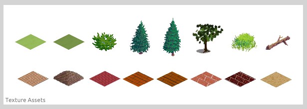
Step 23: Creating Texture Assets
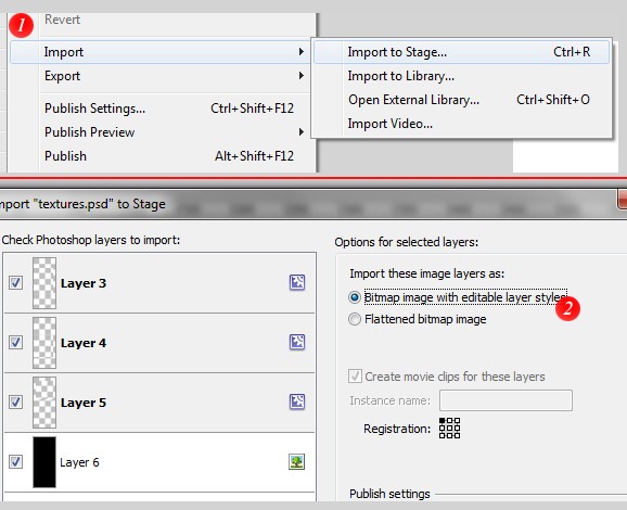
We are going to make our texture assets, so start a new Flash document and import our assets from an image or from a PSD file. From File click Import > Import to Stage, then choose to import the layers as Bitmap image with editable layer styles.
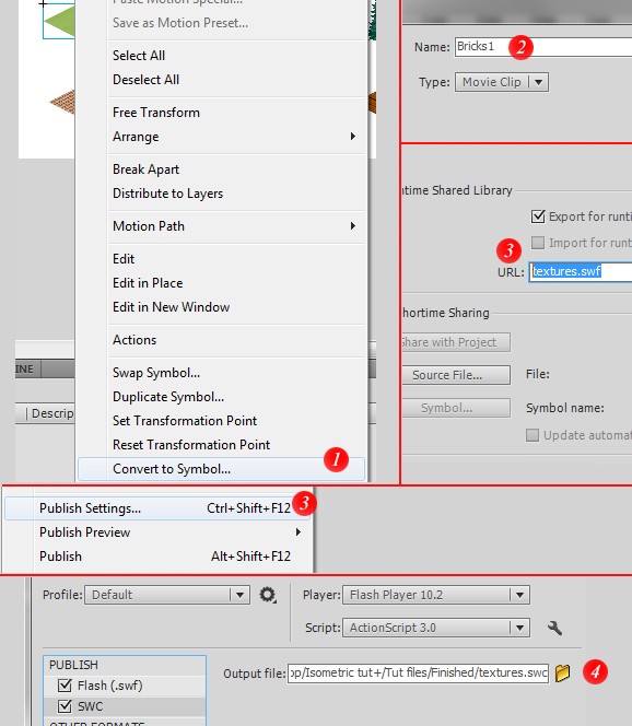
Now we need to convert every bitmap to a movie clip by right clicking on it and choosing Convert to Symbol, then writing its name as in the Bricks and Grass arrays (Brick1, Brick2, etc).
Mark the Export for runtime sharing option and type textures.swf in the URL field. Finally go to File > Publish Settings and mark the SWC option in the PUBLISH section, then click Publish. Now we have a SWC that contains all of our assets, which we can import into our LevelEditor to be used.
Step 24: Importing Texture Assets
It is very simple to import our SWC file. From the File menu click ActionScript Settings, and from the Library path tab click the Flash button which appears in the image below and browse to our SWC.
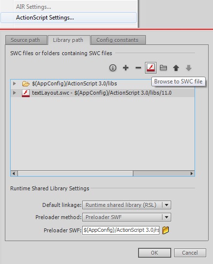
That's it! Now our assets are loaded.
Step 25: The Objects' Mouse Roll Functions
We need to handle mouse events for our objects -- remember in Steps 18 and 19 we added three event listeners for every object. We will implement the ROLL_OVER event listeners in this simple step.
I'd like our objects to have a glow effect when we roll over it, so we need to access the objects themselves. For this, As3isolib has a built-in event type called ProxyEvent which we can use to access the event object using via e.target. We should cast it as IsoDisplayObject (which is the base class for any isometric display object) just to make this event listener as generic as possible, and then add a glow filter using Flash's built-in filters.
The first parameter of the GlowFilter constructor is its color; the second is its alpha, which we'll just set to 1; we will leave the blurX and blurY values at their default, 6, as we don't need any blurring; and finally we'll set the quality to 64.
In the roll out handler we'll just reset the filters.
private function onRollOverHandler(e:ProxyEvent):void
{
   var glow:GlowFilter = new GlowFilter(0xC24704, 1, 6, 6, 64);
   (e.target as IsoDisplayObject).container.filters = [glow];
}
private function onRollOutHandler(e:ProxyEvent):void
{
   (e.target as IsoDisplayObject).container.filters = [];
}
Step 26: Handle Clicks on the Objects
The third event listener for our objects is the CLICK event. What will happen when we click on any object? Well, we need to make a copy of it in the viewport and add a drag-and-drop facility to it, to make it easy for us to move to any place in the scene.
It is very simple to do this. We will first create an object of type IsoDisplayObject and pass it our object that we clicked, just as we did before.
Now we need to clone the clicked object; this is easy, as As3isolib has a built in method called clone(), which belongs to the IsoDisplayObject class, that returns a copy of the cloned object retaining its dimensional and style properties. This will work perfectly for isometric rectangle objects (which we created in the solid color tab), but in the sprites' case (bricks and grass) we need to also copy the sprites array for every object, so we'll do a simple check to see whether the object is of type IsoSprite, and if its sprites property is not null, then we will set the object's sprites property to match the clicked object's sprites.
Then we will move our objects upwards (along the Z-axis) by 50 to avoid overlapping with the grid. Finally we will add three event listeners for our created object: two of them for roll over/out and the last one to handle drag and drop (which we will cover in the next step), then add our object to our scene and render it.
protected function onObjClick(e:ProxyEvent):void
{
            var obj:IsoDisplayObject = e.target as IsoDisplayObject;
            obj = obj.clone();
            if(obj is IsoSprite && (obj as IsoSprite).sprites != null)
            {
                        (obj as IsoSprite).sprites = (e.target as IsoSprite).sprites;
            }
            obj.moveTo(0, 0, 50);
            obj.addEventListener(MouseEvent.ROLL_OVER, onRollOverHandler, false, 0, true);
            obj.addEventListener(MouseEvent.ROLL_OUT, onRollOutHandler, false, 0, true);
            obj.addEventListener(MouseEvent.MOUSE_DOWN, onPickup, false, 0, true);

            scene.addChild(obj);
            scene.render();
}
Step 27: Drag and Drop 1
There is a remaining event listener called onPickup which is a MOUSE_DOWN event to handle the start of dragging. We will start by creating a private variable called dragObject, which will be of type IsoDisplayObject, to use in reference to our dragged object as it appears from its name. Also we will create a point to handle the position of the dragged object.
In the pickup handler we will assign the dragged object to our dragObject variable, then to obtain the current isometric point of the mouse we use the viewPort.localToIso() method. This point will be helpful in calculating the distance between the dragged object and the current mouse position, also it will stop the dragged object from snapping to the mouse position.
Finally we'll remove this event listener, as when our object is picked up we do not want to pick it up again! Instead, we'll add two event listeners for dropping: one to the dragged object and another to the viewPort. Finally, you might ask where the actual move happens; the answer is that it happens in the onMoveObject handler which we will cover in the next and final step.
private var dragObject:IsoDisplayObject;
private var dragPt:Pt;
private function onPickup(e:ProxyEvent):void
{
            dragObject = e.target as IsoDisplayObject;
            dragPt = viewPort.localToIso(new Pt(stage.mouseX, stage.mouseY));
            dragPt.x -= dragObject.x;
            dragPt.y -= dragObject.y;

            dragObject.removeEventListener(MouseEvent.MOUSE_DOWN, onPickup);

            dragObject.addEventListener(MouseEvent.MOUSE_UP, onDrop, false, 0, true);
            viewPort.addEventListener(MouseEvent.MOUSE_UP, onDrop, false, 0, true);
            viewPort.addEventListener(MouseEvent.MOUSE_MOVE, onMoveObject, false, 0, true);
}
Step 28: Drag and Drop 2
The two final event listeners for our Levels Editor are onDrop -- which just removes all the listeners for the dragged object and the viewport, because when an object is dropped these listeners will be useless -- at which point we re-add the onPickup listener for the dragged object to make dragging and dropping available again.
To allow the actual movement of an object, we take a point that corresponds to the mouse position in isometric space and move our object according to the offset between the mouse's original position and its current position.
private function onDrop(e:Event):void
{
            dragObject.removeEventListener(MouseEvent.MOUSE_UP, onDrop);
            viewPort.removeEventListener(MouseEvent.MOUSE_UP, onDrop);
            viewPort.removeEventListener(MouseEvent.MOUSE_MOVE, onMoveObject);

            dragObject.addEventListener(MouseEvent.MOUSE_DOWN, onPickup, false, 0, true);
}
private function onMoveObject(e:MouseEvent):void
{
            var pt:Pt = viewPort.localToIso(new Pt(stage.mouseX, stage.mouseY));

            dragObject.moveTo(pt.x - dragPt.x, pt.y - dragPt.y, dragObject.z);
}
Conclusion
In this tutorial we covered the basics of the open source library As3isolib and creating isometric contents with it like isometric rectangles and sprites. We also covered how to make scenes, cameras and grids, and a lot of useful topics like panning, zooming, dragging and dropping.
Now you can start creating your isometric Flash project with As3isolib. Look out for my next tutorial, about making a game with As3isolib. Hope you have fun!

Comments