Twice a month, we revisit some of our readers’ favorite posts from throughout the history of Activetuts+. This tutorial was first published in April, 2009.
In this tutorial we'll create a magnifying glass effect, demonstrating use of the displacementMapFilter. The effect can be achieved in a relatively short space of time and with very little code.
Final Result Preview
Let's take a look at what we're aiming for:
Step 1: Brief Overview
We're going to work with two layers, plus an additional optional layer. The first will hold an image which will contain the visual graphics, this can be anything. The second layer will be the color map which will control the pixel pushing. The third layer will hold the ActionScript.
An optional fourth layer will be an overlaying graphic acting as the frame or lens surround.
Lets look into it!
Step 2: Document Setup
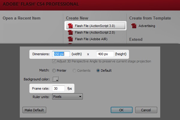
First thing we need to do is make a new ActionScript 3.0 Flash file - make the document size 530px X 400px with a framerate of 30fps.
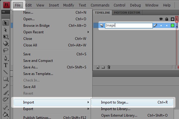
Step 3: Import Resources
Next we need to import an image that we can use for this effect - I found a cool, freely available desktop image at 1024px X 768px.
Import this to stage and name the layer "Image".
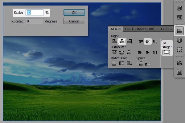
Now let's scale the image down to 50% and center it.
Step 4: Scripting the Filter
Create a new layer on top and call it "Actions". Then let's bring the actions panel out and start coding the effect. First we need the filter for the image so let's create a new filter object and call it "dFilter". We'll leave the filter free of parameters as there are quite a few to set.
var dFilter:DisplacementMapFilter = new DisplacementMapFilter ();
Next we need to set these filter parameters in listed view.
Step 5: Effect Scale
Let's start with the easiest ones and set the scales to around 50. This is the amount to which the magnifier will zoom in. It can also be set to a negative value, but in this case we need it to zoom in, not out.
Additional lines: 3,4
var dFilter:DisplacementMapFilter = new DisplacementMapFilter ();

dFilter.scaleX		= 50
dFilter.scaleY		= 50
Note: this is not the actual order in which the filter normally accepts the parameters. However, in this case we can add them as we wish because we're using the listed view for a better overview.
Step 6: Color Channel Components
Next we'll set the component color channels for X and Y - this dictates which colorchannels in the control map (which we'll create in a second) the filter will listen to.
If you're familiar with the RGB hex code #RRGGBB, we can choose from BitmapDataChannel.RED, BitmapDataChannel.GREEN and BitmapDataChannel.BLUE. To make it easier we can also just write 1 (red), 2 (green) or 4 (blue) - (and no I didn't make a spelling mistake, the blue is 4; this is set from the actual channel position in the hex code). In this example we'll just stick to red (1) and green (2)- but we'll come back to more about this when we design the actual displacement map.
Additional lines: 5,6
var dFilter:DisplacementMapFilter = new DisplacementMapFilter ();

dFilter.scaleX		= 50
dFilter.scaleY		= 50
dFilter.componentX	= 1
dFilter.componentY	= 2
Step 7: Displacement Mode
Next we need to set the mode to determine how the pixels will react if they are pushed further than the image boundaries. Here we can choose from:
DisplacementMapFilterMode.COLOR / DisplacementMapFilterMode.WRAP / DisplacementMapFilterMode.CLAMP / DisplacementMapFilterMode.IGNORE
Again we can simplify this by writing "color", "clamp", "wrap", "ignore". I won't get any further into these in this tutorial, so lets just use "color" which works best in most cases.
Additional lines: 7
var dFilter:DisplacementMapFilter = new DisplacementMapFilter ();

dFilter.scaleX		= 50
dFilter.scaleY		= 50
dFilter.componentX	= 1
dFilter.componentY	= 2
dFilter.mode		= "color"
This mode allows pixels to continue beyond the image boundary (in case the filter pushes the pixels further than the edge of the image).
Step 8: Surrounding Color and Alpha
Now let's set the surrounding color to 0x000000 and alpha to 0. This is 100% transparent, so nothing is displayed outside the image except the source pixels.
Additional lines: 8,9
var dFilter:DisplacementMapFilter = new DisplacementMapFilter ();

dFilter.scaleX		= 50
dFilter.scaleY		= 50
dFilter.componentX	= 1
dFilter.componentY	= 2
dFilter.mode		= "color"
dFilter.color		= 0x000000
dFilter.alpha		= 0
Step 9: Filter Effect Position
Now we need to set the position where the filter will affect the image; our lens position. This has to be set as a Point object containing the x and y value. We'll begin by creating the point object so it's ready for use when we assign it to the displacementMapFilter. Let's call it "dPoint" and set it to 0, 0 as initial values. We'll come back to this in a moment when we need to instruct this point to follow the mouse.
Next we assign "dPoint" to the "dFilter's" point position.
Additional lines: 1,11
var dPoint:Point = new Point(0, 0);

var dFilter:DisplacementMapFilter = new DisplacementMapFilter ();

dFilter.scaleX		= 50
dFilter.scaleY		= 50
dFilter.componentX	= 1
dFilter.componentY	= 2
dFilter.mode		= "color"
dFilter.color		= 0x000000
dFilter.alpha		= 0
dFilter.mapPoint	= dPoint;
Step 10: BitmapData
Last but not least we need to assign the control map to the filter. This is the map which contains the colored pixels that the componentX and Y listen to.
Additional lines: 13
var dPoint:Point = new Point(0, 0);

var dFilter:DisplacementMapFilter = new DisplacementMapFilter ();

dFilter.scaleX		= 50
dFilter.scaleY		= 50
dFilter.componentX	= 1
dFilter.componentY	= 2
dFilter.mode		= "color"
dFilter.color		= 0x000000
dFilter.alpha		= 0
dFilter.mapPoint	= dPoint;
dFilter.mapBitmap	=
Here we also need a BitmapData object to act as a data container for our color-map.
Step 11: Designing the Color Map
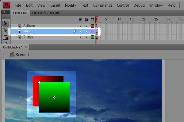
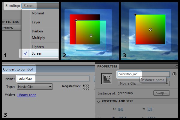
First we create a 100px X 100px, red to black, linear gradient square. This will take the current pixels and push them left and right as we set the componentX to red. Let's make this a movieclip called "redMap"
Then we do the same again - but this time with a green to black linear gradient square, again 100px X 100px. This time we'll also rotate it 90°. You might remember we set the component for the Y axis displacement as green (componentY = 2) so the gradient goes along the y axis. Once again we'll convert it to a movieclip, this time calling it "greenMap"
Step 12: Preparing the Map for Capture Phase
We now have two separate color images; we need just one, so set the blendmode of the greenMap to "screen". Every color from the greenMap will then shine through on the redMap. Place the greenMap on top of the redMap and make sure they align correctly.
Select both movieclips by clicking on the layer "Map" and convert the two into one movieclip called "colorMap". Then set the instance name to "colorMap_mc".
Step 13: Map Container
Now let's return to the code and continue by capturing the colorMap movieclip in a bitmapData.
Go to the top of the code and create a new BitmapData object. Let's call it "dMap" and set the size of it to match the size of our colorMap (in this case 100px X 100px, but this can be almost anything). We'll set transparent to "true" and color to 0x808080. This ensures that any remaining pixels in the bitmapData are neutral.
Additional lines: 3
var dPoint:Point = new Point(0, 0);

var dMap:BitmapData = new BitmapData(colorMap_mc.width, colorMap_mc.height, true, 0x808080)

var dFilter:DisplacementMapFilter = new DisplacementMapFilter ();

dFilter.scaleX		= 50
dFilter.scaleY		= 50
dFilter.componentX	= 1
dFilter.componentY	= 2
dFilter.mode		= "color"
dFilter.color		= 0x000000
dFilter.alpha		= 0
dFilter.mapPoint	= dPoint;
dFilter.mapBitmap	=
Step 14: Capture Phase
We need to draw the colorMap's content into the bitmapData. Once that's done, we'll be able to use script to delete the colorMap from the stage. This is possible as the colorMap image will be contained within the bitmapData code.
Additional lines: 5, 7
var dPoint:Point = new Point(0, 0);

var dMap:BitmapData = new BitmapData(colorMap_mc.width, colorMap_mc.height, true, 0x808080)

dMap.draw(colorMap_mc)

removeChild(colorMap_mc)

var dFilter:DisplacementMapFilter = new DisplacementMapFilter ();

dFilter.scaleX		= 50
dFilter.scaleY		= 50
dFilter.componentX	= 1
dFilter.componentY	= 2
dFilter.mode		= "color"
dFilter.color		= 0x000000
dFilter.alpha		= 0
dFilter.mapPoint	= dPoint;
dFilter.mapBitmap	=
Step 15: Assigning the Map to the Filter
Add the bitmapData dMap to the displacementMapFilter by setting the last parameter in the list (mapBitmap) to "dMap".
Modified lines: 19
var dPoint:Point = new Point(0, 0);

var dMap:BitmapData = new BitmapData(colorMap_mc.width, colorMap_mc.height, true, 0x808080)

dMap.draw(colorMap_mc)

removeChild(colorMap_mc)

var dFilter:DisplacementMapFilter = new DisplacementMapFilter ();

dFilter.scaleX		= 50
dFilter.scaleY		= 50
dFilter.componentX	= 1
dFilter.componentY	= 2
dFilter.mode		= "color"
dFilter.color		= 0x000000
dFilter.alpha		= 0
dFilter.mapPoint	= dPoint
dFilter.mapBitmap	= dMap
Step 16: Add Filter to Image
The filter is complete! We now need to add it to the image, so select the image and make sure it has an instance name - lets call it "Image_mc". That done, we're able to set the filter on the image. We do this at the end of the code by setting the Image filters parameter as an array like this:
Image_mc.filters = [dFilter]
Additional lines: 21
var dPoint:Point = new Point(0, 0);

var dMap:BitmapData = new BitmapData(colorMap_mc.width, colorMap_mc.height, true, 0x808080)

dMap.draw(colorMap_mc)

removeChild(colorMap_mc)

var dFilter:DisplacementMapFilter = new DisplacementMapFilter ();

dFilter.scaleX		= 50
dFilter.scaleY		= 50
dFilter.componentX	= 1
dFilter.componentY	= 2
dFilter.mode		= "color"
dFilter.color		= 0x000000
dFilter.alpha		= 0
dFilter.mapPoint	= dPoint
dFilter.mapBitmap	= dMap

Image_mc.filters = [dFilter]
OK, let's export the movie and see how the filter is affecting the image. It should look something like this:
Step 17: Interactivity
What we have so far isn't very exciting, so let's try to make the lens follow the mouse.
First we add the "enterFrame" loop code like this:
Additional lines: 23,25,27
var dPoint:Point = new Point(0, 0);

var dMap:BitmapData = new BitmapData(colorMap_mc.width, colorMap_mc.height, true, 0x808080)

dMap.draw(colorMap_mc)

removeChild(colorMap_mc)

var dFilter:DisplacementMapFilter = new DisplacementMapFilter ();

dFilter.scaleX		= 50
dFilter.scaleY		= 50
dFilter.componentX	= 1
dFilter.componentY	= 2
dFilter.mode		= "color"
dFilter.color		= 0x000000
dFilter.alpha		= 0
dFilter.mapPoint	= dPoint
dFilter.mapBitmap	= dMap

Image_mc.filters = [dFilter]

Image_mc.addEventListener(Event.ENTER_FRAME, onFrame)

function onFrame(e:Event){

}
Step 18: Follow the Mouse
Next we set the values of our dPoint's X and Y to follow the mouse. Additionally, we'll reassign the newly changed dPoint to the dFilter again and reassign the filter to the image.
Additional lines: 26,27,28,29
var dPoint:Point = new Point(0, 0);

var dMap:BitmapData = new BitmapData(colorMap_mc.width, colorMap_mc.height, true, 0x808080)

dMap.draw(colorMap_mc)

removeChild(colorMap_mc)

var dFilter:DisplacementMapFilter = new DisplacementMapFilter ();

dFilter.scaleX		= 50
dFilter.scaleY		= 50
dFilter.componentX	= 1
dFilter.componentY	= 2
dFilter.mode		= "color"
dFilter.color		= 0x000000
dFilter.alpha		= 0
dFilter.mapPoint	= dPoint
dFilter.mapBitmap	= dMap

Image_mc.filters = [dFilter]

Image_mc.addEventListener(Event.ENTER_FRAME, onFrame)

function onFrame(e:Event){
	dPoint.x = mouseX
	dPoint.y = mouseY
	dFilter.mapPoint = dPoint
	Image_mc.filters = [dFilter]
}
Lets test it again. It should look like this:
Step 19: Finalizing
It's still not exactly how we want it, so lets make the center of the displacement follow the mouse and also add a small easing to the movement. To do that we change the following code:
dPoint.x = mouseXdPoint.y = mouseY
Modified lines: 26,27
var dPoint:Point = new Point(0, 0);

var dMap:BitmapData = new BitmapData(colorMap_mc.width, colorMap_mc.height, true, 0x808080)

dMap.draw(colorMap_mc)

removeChild(colorMap_mc)

var dFilter:DisplacementMapFilter = new DisplacementMapFilter ();

dFilter.scaleX 		= 50
dFilter.scaleY 		= 50
dFilter.componentX 	= 1
dFilter.componentY 	= 2
dFilter.mode		= "color"
dFilter.color		= 0x000000
dFilter.alpha 		= 0
dFilter.mapPoint	= dPoint
dFilter.mapBitmap	= dMap

Image_mc.filters = [dFilter]

Image_mc.addEventListener(Event.ENTER_FRAME, onFrame)

function onFrame(e:Event){
	dPoint.x += ((mouseX-colorMap_mc.width/2)-dPoint.x)*0.3
	dPoint.y += ((mouseY-colorMap_mc.height/2)-dPoint.y)*0.3
	dFilter.mapPoint = dPoint
	Image_mc.filters = [dFilter]
}
To sum up: we subtract half the size of the map from the map position, so it centers. Then we add a basic tweening function, which can be written like this:
this += (that-this)*speed
Step 20: Adding Custom Graphics
To top it off, I added a magnifying glass graphic that I prepared in photoshop. I converted it into a movieclip, gave it an instance name and made it follow the point that we use for the displacemenMapFilter.
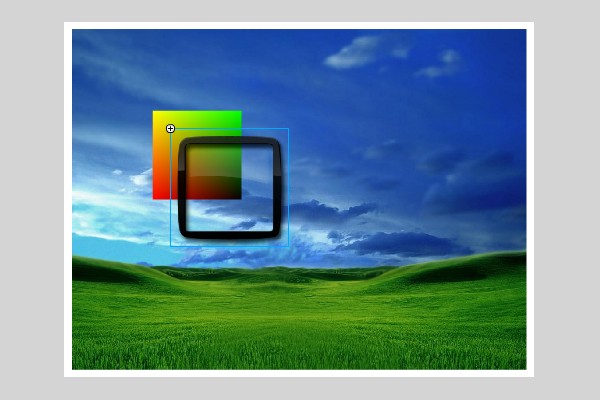
This is achieved by setting the new lens_frame_image X and Y position equal to the dPoint position. Then subtract the offset for the graphics edge, so that it aligns perfectly with the filter effect.
Additional lines: 4,5
function onFrame(e:Event){
	dPoint.x += ((mouseX-colorMap_mc.width/2)-dPoint.x)*0.3
	dPoint.y += ((mouseY-colorMap_mc.height/2)-dPoint.y)*0.3
	lens_mc.x = dPoint.x-8
	lens_mc.y = dPoint.y-8
	dFilter.mapPoint = dPoint
	Image_mc.filters = [dFilter]
}
Now our result should look like this:
Conclusion
When you have learned to create this effect yourself it shouldn't take more than 15 minutes to set up. Remember; if you forget what the parameters for the displacementMapFilter are you can always look them up on "help". There you will get the listed order and what each parameter does.
For quick experimentation you can go to my website and look in the "flash" section under "test / labs" - I have a bunch of displacementMapFilter test environments you can try out.
I hope you can find use for this filter in your creative work!

Comments