Almost every Android phone available in the market today has a graphics processing unit, or GPU for short. As its name suggests, this is a hardware unit dedicated to handling calculations that are usually related to 3D graphics. As an app developer, you can make use of the GPU to create complex graphics and animations that run at very high frame rates.
There are currently two different APIs you can use to interact with an Android device's GPU: Vulkan and OpenGL ES. While Vulkan is available only on devices running Android 7.0 or higher, OpenGL ES is supported by all Android versions.
In this tutorial, I'll help you get started with using OpenGL ES 2.0 in Android apps.
Prerequisites
To be able to follow this tutorial, you'll need:
- the latest version of Android Studio
- an Android device that supports OpenGL ES 2.0 or higher
- a recent version of Blender, or any other 3D modeling software
1. What Is OpenGL ES?
OpenGL, which is short for Open Graphics Library, is a platform-independent API that allows you to create hardware-accelerated 3D graphics. OpenGL ES, short for OpenGL for Embedded Systems, is a subset of the API.
OpenGL ES is a very low-level API. In other words, it doesn't offer any methods that allow you to quickly create or manipulate 3D objects. Instead, while working with it, you are expected to manually manage tasks such as creating the individual vertices and faces of 3D objects, calculating various 3D transformations, and creating different types of shaders.
It is also worth mentioning that the Android SDK and NDK together allow you to write OpenGL ES-related code in both Java and C.
2. Project Setup
Because the OpenGL ES APIs are a part of the Android framework, you don't have to add any dependencies to your project to be able to use them. In this tutorial, however, we'll be using the Apache Commons IO library to read the contents of a few text files. Therefore, add it as a compile dependency in your app module's build.gradle file:
compile 'commons-io:commons-io:2.5'
Additionally, in order to stop Google Play users who do not have devices that support the OpenGL ES version you need from installing your app, add the following <uses-feature> tag to your project's manifest file:
<uses-feature android:glEsVersion="0x00020000"
              android:required="true" />
3. Create a Canvas
The Android framework offers two widgets that can act as a canvas for your 3D graphics: GLSurfaceView and TextureView. Most developers prefer using GLSurfaceView, and choose TextureView only when they intend to overlay their 3D graphics on another View widget. For the app we will be creating in this tutorial, GLSurfaceView will suffice.
Adding a GLSurfaceView widget to your layout file is no different from adding any other widget.
<android.opengl.GLSurfaceView
    android:layout_width="300dp"
    android:layout_height="300dp"
    android:id="@+id/my_surface_view"
    />
Note that we've made the width of our widget equal to its height. Doing so is important because the OpenGL ES coordinate system is a square. If you must use a rectangular canvas, do remember to include its aspect ratio while calculating your projection matrix. You'll learn what a projection matrix is in a later step.
Initializing a GLSurfaceView widget inside an Activity class is as simple as calling the findViewById() method and passing its id to it.
mySurfaceView = (GLSurfaceView)findViewById(R.id.my_surface_view);
Additionally, we must call the setEGLContextClientVersion() method to explicitly specify the version of OpenGL ES we'll be using to draw inside the widget.
mySurfaceView.setEGLContextClientVersion(2);
4. Create a 3D Object
Although it is possible to create 3D objects in Java by hand-coding the X, Y, and Z coordinates of all their vertices, doing so is very cumbersome. Using 3D modeling tools instead is far easier. Blender is one such tool. It is open source, powerful, and very easy to learn.
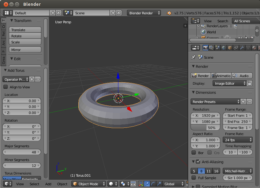
Fire up Blender and press X to delete the default cube. Next, press Shift-A and select Mesh > Torus. We now have a fairly complex 3D object consisting of 576 vertices.
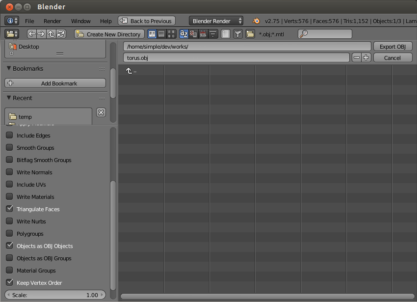
To be able to use the torus in our Android app, we must export it as a Wavefront OBJ file. Therefore, go to File > Export > Wavefront (.obj). In the next screen, give a name to the OBJ file, make sure that the Triangulate Faces and Keep Vertex Order options are selected, and press the Export OBJ button.
You can now close Blender and move the OBJ file to your Android Studio project's assets folder.
5. Parse the OBJ File
If you haven't noticed already, the OBJ file we created in the previous step is a text file, which can be opened using any text editor.
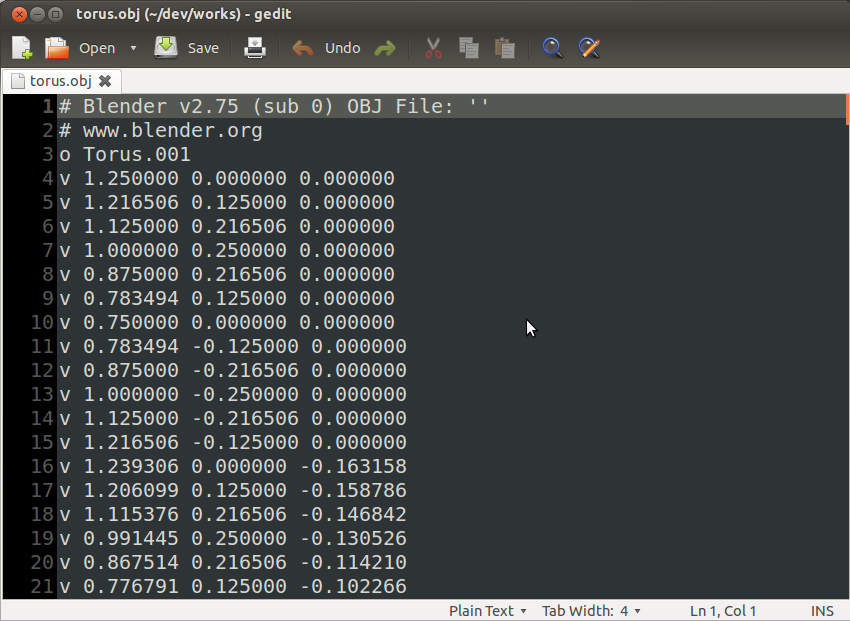
In the file, each line that starts with a "v" represents a single vertex. Similarly, each line starting with an "f" represents a single triangular face. While each vertex line contains the X, Y, and Z coordinates of a vertex, each face line contains the indices of three vertices, which together form a face. That's all you need to know to parse an OBJ file.
Before you begin, create a new Java class called Torus and add two List objects, one for the vertices and one for the faces, as its member variables.
public class Torus {

    private List<String> verticesList;
    private List<String> facesList;

    public Torus(Context context) {
        verticesList = new ArrayList<>();
        facesList = new ArrayList<>();

        // More code goes here
    }

}
The easiest way to read all the individual lines of the OBJ file is to use the Scanner class and its nextLine() method. While looping through the lines and populating the two lists, you can use the String class's startsWith() method to check if the current line starts with a "v" or an "f".
// Open the OBJ file with a Scanner
Scanner scanner = new Scanner(context.getAssets().open("torus.obj"));

// Loop through all its lines
while(scanner.hasNextLine()) {
    String line = scanner.nextLine();
    if(line.startsWith("v ")) {
        // Add vertex line to list of vertices
        verticesList.add(line);
    } else if(line.startsWith("f ")) {
        // Add face line to faces list
        facesList.add(line);
    }
}

// Close the scanner
scanner.close();
6. Create Buffer Objects
You can't pass the lists of vertices and faces to the methods available in the OpenGL ES API directly. You must first convert them into buffer objects. To store the vertex coordinate data, we'll need a FloatBuffer object. For the face data, which simply consists of vertex indices, a ShortBuffer object will suffice.
Accordingly, add the following member variables to the Torus class:
private FloatBuffer verticesBuffer;
private ShortBuffer facesBuffer;
To initialize the buffers, we must first create a ByteBuffer object using the allocateDirect() method. For the vertices buffer, allocate four bytes for each coordinate, what with the coordinates being floating-point numbers. Once the ByteBuffer object has been created, you can convert it into a FloatBuffer by calling its asFloatBuffer() method.
// Create buffer for vertices
ByteBuffer buffer1 = ByteBuffer.allocateDirect(verticesList.size() * 3 * 4);
buffer1.order(ByteOrder.nativeOrder());
verticesBuffer = buffer1.asFloatBuffer();
Similarly, create another ByteBuffer object for the faces buffer. This time, allocate two bytes for each vertex index because the indices are unsigned short literals. Also, make sure that you use the asShortBuffer() method to convert the ByteBuffer object to a ShortBuffer.
// Create buffer for faces
ByteBuffer buffer2 = ByteBuffer.allocateDirect(facesList.size() * 3 * 2);
buffer2.order(ByteOrder.nativeOrder());
facesBuffer = buffer2.asShortBuffer();
Populating the vertices buffer involves looping through the contents of verticesList, extracting the X, Y, and Z coordinates from each item, and calling the put() method to put data inside the buffer. Because verticesList contains only strings, we must use the parseFloat() to convert the coordinates from strings to float values.
for(String vertex: verticesList) {
    String coords[] = vertex.split(" "); // Split by space
    float x = Float.parseFloat(coords[1]);
    float y = Float.parseFloat(coords[2]);
    float z = Float.parseFloat(coords[3]);
    verticesBuffer.put(x);
    verticesBuffer.put(y);
    verticesBuffer.put(z);
}
verticesBuffer.position(0);
Note that in the above code we've used the position() method to reset the position of the buffer.
Populating the faces buffer is slightly different. You must use the parseShort() method to convert each vertex index to a short value. Additionally, because the indices start from one instead of zero, you must remember to subtract one from them before putting them inside the buffer.
for(String face: facesList) {
    String vertexIndices[] = face.split(" ");
    short vertex1 = Short.parseShort(vertexIndices[1]);
    short vertex2 = Short.parseShort(vertexIndices[2]);
    short vertex3 = Short.parseShort(vertexIndices[3]);
    facesBuffer.put((short)(vertex1 - 1));
    facesBuffer.put((short)(vertex2 - 1));
    facesBuffer.put((short)(vertex3 - 1));
}
facesBuffer.position(0);
7. Create Shaders
To be able to render our 3D object, we must create a vertex shader and a fragment shader for it. For now, you can think of a shader as a very simple program written in a C-like language called OpenGL Shading Language, or GLSL for short.
A vertex shader, as you might have guessed, is responsible for handling a 3D object's vertices. A fragment shader, also called a pixel shader, is responsible for coloring the 3D object's pixels.
Step 1: Create a Vertex Shader
Create a new file called vertex_shader.txt inside your project's res/raw folder.
A vertex shader must have an attribute global variable inside it in order to receive vertex position data from your Java code. Additionally, add a uniform global variable to receive a view-projection matrix from the Java code.
Inside the main() function of the vertex shader, you must set the value of gl_position, a GLSL built-in variable that decides the final position of the vertex. For now, you can simply set its value to the product of the uniform and attribute global variables.
Accordingly, add the following code to the file:
attribute vec4 position;
uniform mat4 matrix;

void main() {
    gl_Position = matrix * position;
}
Step 2: Create a Fragment Shader
Create a new file called fragment_shader.txt inside your project's res/raw folder.
To keep this tutorial short, we'll now be creating a very minimalist fragment shader that simply assigns the color orange to all pixels. To assign a color to a pixel, inside the main() function of a fragment shader, you can use the gl_FragColor built-in variable.
precision mediump float;

void main() {
    gl_FragColor = vec4(1, 0.5, 0, 1.0);
}
In the above code, the first line specifying the precision of floating-point numbers is important because a fragment shader doesn't have any default precision for them.
Step 3: Compile the Shaders
Back in the Torus class, you must now add code to compile the two shaders you created. Before you do so, however, you must convert them from raw resources to strings. The IOUtils class, which is a part of the Apache Commons IO library, has a toString() method for doing just that. The following code shows you how to use it:
// Convert vertex_shader.txt to a string
InputStream vertexShaderStream =
        context.getResources().openRawResource(R.raw.vertex_shader);
String vertexShaderCode =
        IOUtils.toString(vertexShaderStream, Charset.defaultCharset());
vertexShaderStream.close();

// Convert fragment_shader.txt to a string
InputStream fragmentShaderStream =
        context.getResources().openRawResource(R.raw.fragment_shader);
String fragmentShaderCode =
        IOUtils.toString(fragmentShaderStream, Charset.defaultCharset());
fragmentShaderStream.close();
The shaders' code must be added to OpenGL ES shader objects. To create a new shader object, use the glCreateShader() method of the GLES20 class. Depending on the type of shader object you want to create, you can either pass GL_VERTEX_SHADER or GL_FRAGMENT_SHADER to it. The method returns an integer that serves as a reference to the shader object. A newly-created shader object doesn't contain any code. To add the shader code to the shader object, you must use the glShaderSource() method.
The following code creates shader objects for both the vertex shader and the fragment shader:
int vertexShader = GLES20.glCreateShader(GLES20.GL_VERTEX_SHADER);
GLES20.glShaderSource(vertexShader, vertexShaderCode);

int fragmentShader = GLES20.glCreateShader(GLES20.GL_FRAGMENT_SHADER);
GLES20.glShaderSource(fragmentShader, fragmentShaderCode);
We can now pass the shader objects to the glCompileShader() method to compile the code they contain.
GLES20.glCompileShader(vertexShader);
GLES20.glCompileShader(fragmentShader);
8. Create a Program
While rendering a 3D object, you don't use the shaders directly. Instead, you attach them to a program and use the program. Therefore, add a member variable to the Torus class to store a reference to an OpenGL ES program.
private int program;
To create a new program, use the glCreateProgram() method. To attach the vertex and fragment shader objects to it, use the glAttachShader() method.
program = GLES20.glCreateProgram();
GLES20.glAttachShader(program, vertexShader);
GLES20.glAttachShader(program, fragmentShader);
At this point, you can link the program and start using it. To do so, use the glLinkProgram() and glUseProgram() methods.
GLES20.glLinkProgram(program);
GLES20.glUseProgram(program);
9. Draw the 3D Object
With the shaders and buffers ready, we have everything we need to draw our torus. Add a new method to the Torus class called draw:
public void draw() {
    // Drawing code goes here
}
In an earlier step, inside the vertex shader, we defined a position variable to receive vertex position data from Java code. It is now time to send the vertex position data to it. To do so, we must first get a handle to the position variable in our Java code using the glGetAttribLocation() method. Additionally, the handle must be enabled using the glEnableVertexAttribArray() method.
Accordingly, add the following code inside the draw() method:
int position = GLES20.glGetAttribLocation(program, "position");
GLES20.glEnableVertexAttribArray(position);
To point the position handle to our vertices buffer, we must use the glVertexAttribPointer() method. In addition to the vertices buffer itself, the method expects the number of coordinates per vertex, the type of the coordinates, and the byte offset for each vertex. Because we have three coordinates per vertex and each coordinate is a float, the byte offset must be 3 * 4.
GLES20.glVertexAttribPointer(position,
            3, GLES20.GL_FLOAT, false, 3 * 4, verticesBuffer);
Our vertex shader also expects a view-projection matrix. Although such a matrix is not always necessary, using one allows you to have better control over how your 3D object is rendered.
A view-projection matrix is simply the product of the view and projection matrices. A view matrix allows you to specify the locations of your camera and the point it is looking at. A projection matrix, on the other hand, allows you to not only map the square coordinate system of OpenGL ES to the rectangular screen of an Android device, but also specify the near and far planes of the viewing frustum.
To create the matrices, you can simply create three float arrays of size 16:
float[] projectionMatrix = new float[16];
float[] viewMatrix = new float[16];

float[] productMatrix = new float[16];
To initialize the projection matrix, you can use the frustumM() method of the Matrix class. It expects the locations of the left, right, bottom, top, near, and far clip planes. Because our canvas is a square already, you can use the values -1 and 1 for the left and right, and the bottom and top clip planes. For the near and far clip planes, feel free to experiment with different values.
Matrix.frustumM(projectionMatrix, 0,
                -1, 1,
                -1, 1,
                 2, 9);
To initialize the view matrix, use the setLookAtM() method. It expects the positions of the camera and the point it is looking at. You are again free to experiment with different values.
Matrix.setLookAtM(viewMatrix, 0,
                  0, 3, -4,
                  0, 0, 0,
                  0, 1, 0);
Finally, to calculate the product matrix, use the multiplyMM() method.
Matrix.multiplyMM(productMatrix, 0,
                  projectionMatrix, 0,
                  viewMatrix, 0);
To pass the product matrix to the vertex shader, you must get a handle to its matrix variable using the glGetUniformLocation() method. Once you have the handle, you can point it to the product matrix using the glUniformMatrix() method.
int matrix = GLES20.glGetUniformLocation(program, "matrix");
GLES20.glUniformMatrix4fv(matrix, 1, false, productMatrix, 0);
You must have noticed that we still haven't used the faces buffer. That means that we still haven't told OpenGL ES how to connect the vertices to form triangles, which will serve as the faces of our 3D object.
The glDrawElements() method allows you to use the faces buffer to create triangles. As its arguments, it expects the total number of vertex indices, the type of each index, and the faces buffer.
GLES20.glDrawElements(GLES20.GL_TRIANGLES,
        facesList.size() * 3, GLES20.GL_UNSIGNED_SHORT, facesBuffer);
Lastly, do remember to disable the attribute handler you enabled earlier to pass the vertex data to the vertex shader.
GLES20.glDisableVertexAttribArray(position);
10. Create a Renderer
Our GLSurfaceView widget needs a GLSurfaceView.Renderer object to be able to render 3D graphics. You can use the setRenderer() to associate a renderer with it.
mySurfaceView.setRenderer(new GLSurfaceView.Renderer() {
    // More code goes here
});
Inside the onSurfaceCreated() method of the renderer, you must specify how often the 3D graphic must be rendered. For now, let's render only when the 3D graphic changes. To do so, pass the RENDERMODE_WHEN_DIRTY constant to the setRenderMode() method. Additionally, initialize a new instance of the Torus object.
@Override
public void onSurfaceCreated(GL10 gl10, EGLConfig eglConfig) {
    mySurfaceView.setRenderMode(GLSurfaceView.RENDERMODE_WHEN_DIRTY);
    torus = new Torus(getApplicationContext());
}
Inside the onSurfaceChanged() method of the renderer, you can define the width and height of your viewport using the glViewport() method.
@Override
public void onSurfaceChanged(GL10 gl10, int width, int height) {
    GLES20.glViewport(0,0, width, height);
}
Inside the onDrawFrame() method of the renderer, add a call to the draw() method of the Torus class to actually draw the torus.
@Override
public void onDrawFrame(GL10 gl10) {
    torus.draw();
}
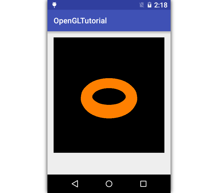
At this point, you can run your app to see the orange torus.
Conclusion
You now know how to use OpenGL ES in Android apps. In this tutorial, you also learned how to parse a Wavefront OBJ file and extract vertex and face data from it. I suggest you generate a few more 3D objects using Blender and try rendering them in the app.
Although we focused only on OpenGL ES 2.0, do understand that OpenGL ES 3.x is backwards-compatible with OpenGL ES 2.0. That means that if you prefer using OpenGL ES 3.x in your app, you can simply replace the GLES20 class with the GLES30 or GLES31 classes.
To learn more about OpenGL ES, you can refer to its reference pages. And to learn more about Android app development, be sure to check out some of our other tutorials here at Envato Tuts+!

How to Get Started With Android's Native Development Kit

Android Things: Peripheral Input/Output

How to Secure an Android App

Coding an Android App With Flutter and Dart

Comments