Introduction
Graphical resources in the digital world are of two basic types, raster and vector. Raster images are essentially a rectangular array of pixel intensities. Vector graphics, on the other hand, are mathematical representations of shapes.
While there are situations in which raster images are irreplaceable (photos, for example), in other scenarios, vector graphics make capable substitutes. Vector graphics make the task of creating graphical resources for multiple screen resolutions trivial. At the time of writing, there are at least half a dozen screen resolutions to contend with on the iOS platform.
One of the best things about vector graphics is that they can be rendered to any resolution while remaining absolutely crisp and smooth. This is why PostScript and TrueType fonts look sharp at any magnification. Because smartphone and computer displays are raster in nature, ultimately, the vector image does need to be rendered to the display as a raster image at the appropriate resolution. This is usually taken care of by the low-level graphics library and the programmer doesn’t need to worry about this.
1. When to Use Vector Graphics?
Let’s take a look at some scenarios where you should consider using vector graphics.
App and Menu Icons, User Interface Elements
A few years ago, Apple eschewed skeuomorphism in the user interface of its apps and iOS itself, in favour of bold and geometrically precise designs. Take a look at the Camera or Photo app icons, for example.
More likely than not, they were designed using vector graphics tools. Developers had to follow suit and most of the popular (non-game) apps underwent a complete metamorphosis in order to conform to this design paradigm.
Games
Games with simple graphics (think Asteroids) or geometric themes (Super Hexagon and Geometry Jump come to mind) can have their sprites rendered from vectors. The same applies to games that have procedurally generated levels.
Images
Images in which you want to inject a small amount of randomness to get multiple versions of the same basic shape.
2. Bezier Curves
What are Bezier curves? Without delving into the mathematical theory, let’s just talk about the features that are of practical use to developers.
Degrees of Freedom
Bezier curves are characterized by how many degrees of freedom they have. The higher this degree, the more variation the curve can incorporate (but also the more mathematically complex it is).
Degree one Beziers are straight line segments. Degree two curves are called quad curves. Degree three curves (cubics) are the ones we’ll focus on, because they offer a good compromise between flexibility and complexity.
Cubic Beziers can represent not only simple smooth curves, but also loops and cusps. Several cubic Bezier segments can be hooked up end to end to form more complicated shapes.
Cubic Beziers
A cubic Bezier is defined by its two end points and two additional control points that determine its shape. In general, a degree n Bezier has (n-1) control points, not counting the end points.
An attractive feature of cubic Beziers is that these points have a significant visual intepretation. The line connecting an end point to its adjacent control point acts as a tangent to the curve at the end point. This fact is useful for designing shapes. We’ll exploit this property later in the tutorial.
Geometric Transforms
Because of the mathematical nature of these curves, you can easily apply geometric transforms to them, such as scaling, rotation, and translation, without any loss of fidelity.
The following image shows a sampling of different kinds of shapes that a single cubic Bezier can take. Notice how the green line segments act as tangents to the curve.

3. Core Graphics and the UIBezierPath Class
On iOS and OS X, vector graphics are implemented using the C-based Core Graphics library. Built on top of this is UIKit/Cocoa, which adds a veneer of object orientation. The workhorse is the UIBezierPath class (NSBezierPath on OS X), an implementation of a mathematical Bezier curve.
The UIBezierPath class supports Bezier curves of degree one (straight line segments), two (quad curves), and three (cubic curves).
Programmatically, a UIBezierPath object can be built piece-by-piece by appending new components (subpaths) to it. To facilitate this, the UIBezierPath object keeps track of the currentPoint property. Every time you append a new path segment, the last point of the appended segment becomes the current point. Any additional drawing you do generally starts at this point. You can explicitly move this point to a desired location.
The class has convenience methods for making commonly used shapes, such as arcs and circles, (rounded) rectangles, etc. Internally, these shapes have been built by connecting several subpaths.
The overall path can be either an open or closed shape. It can even be self-intersecting or have multiple closed components.
4. Getting started
This tutorial is meant to serve as a beyond-the-basics look at vector graphics generation. But even if you are an experienced developer who hasn’t used Core Graphics or UIBezierPath before, you should be able to follow along. If you’re new to this, I recommend skimming through the UIBezierPath class reference (and the underlying Core Graphics functions) if you’re not already familiar with it. We can only exercise a limited number of features of the API in a single tutorial.
Enough talk. Let’s start coding. In the remainder of this tutorial, I will present two scenarios where vector graphics are the ideal tool to use.
Fire up Xcode, create a new playground, and set the platform to iOS. Incidently, Xcode playgrounds are another reason why working with vector graphics is now fun. You can tweak your code and get instant visual feedback. Note that you should be using the latest stable version of Xcode, which is 7.2 at the time of this writing.
Scenario 1: Making Cloud Shapes
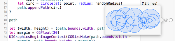
We’d like to generate images of clouds that adhere to a basic cloud shape while having some randomness so that each cloud looks different. The basic design I’ve settled on is a compound shape, defined by several circles of random radii centered along an elliptical path of random size (within appropriate ranges).
To clarify, here’s what the overall object looks like if we stroked the vector path instead of filling it.

If your geometry is a bit rusty, then this Wikipedia image shows what an ellipse looks like.

Some Utility Functions
Let’s start by writing a couple of helper functions.
import UIKit

func randomInt(lower lower: Int, upper: Int) -> Int {
    assert(lower < upper)
    return lower + Int(arc4random_uniform(UInt32(upper - lower)))
}

func circle(at center: CGPoint, radius: CGFloat) -> UIBezierPath {
    return UIBezierPath(arcCenter: center, radius: radius, startAngle: 0, endAngle: CGFloat(2 * M_PI), clockwise: true)
}
The random(lower:upper:) function uses the built-in arc4random_uniform() function to generate random numbers in the range lower and (upper-1). The circle(at:center:) function generates a Bezier path, representing a circle with a given center and radius.
Generating Points and Paths
Let’s now focus on generating the points along the elliptical path. An ellipse centered at the origin of the coordinate system with its axes aligned along the coordinate axes has a particularly simple mathematical form that looks like this.
P(r, θ) = (a cos(θ), b sin(θ))
We assign random values for the lengths of its major and minor axis so that the shape looks like a cloud, more elongated horizontally than vertically.
We use the stride() function to generate regularly spaced angles around the circle, and then use map() to generate regularly spaced points on the ellipse using the above mathematical expression.
let a = Double(randomInt(lower: 70, upper: 100))
    let b = Double(randomInt(lower: 10, upper: 35))
    let ndiv = 12 as Double


    let points = (0.0).stride(to: 1.0, by: 1/ndiv).map { CGPoint(x: a * cos(2 * M_PI * $0), y: b * sin(2 * M_PI * $0)) }
We generate the central “mass” of the cloud by joining the points along the elliptical path. If we don’t, we’ll get a big void at the center.
let path = UIBezierPath()
path.moveToPoint(points[0])

for point in points[1..<points.count] {
    path.addLineToPoint(point)
}

path.closePath()
Note that the exact path doesn’t matter, because we’ll be filling the path, not stroking it. This means that it won’t be distinguishable from the circles.
To generate the circles, we first heuristically choose a range for the random circle radii. The fact that we’re developing this in a playground helped me play with the values until I got a result I was satisfied with.
let minRadius = (Int)(M_PI * a/ndiv)
let maxRadius = minRadius + 25

for point in points[0..<points.count] {
    let randomRadius = CGFloat(randomInt(lower: minRadius, upper: maxRadius))
    let circ = circle(at: point, radius: randomRadius)
    path.appendPath(circ)
}

path
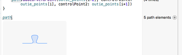
Previewing the Result
You can view the result by clicking the “eye” icon in the results panel on the right, on the same line as the “path” statement.
Final Touches
How do we rasterize this to get the final result? We need what’s known as a “graphical context” in which to draw the paths. In our case, we’ll be drawing into an image (a UIImage instance). It is at this point that you need to set several parameters that specify what the final path will be rendered as, such as colors and stroke widths. Finally, you stroke or fill your path (or both). In our case, we want our clouds to be white, and we only want to fill them.
Let’s package this code into a function so we can generate as many clouds as we wish. And while we’re at it, we’ll write some code to draw a few random clouds on a blue background (representing the sky) and to draw all this into the playground live view.
Here’s the final code:
import UIKit
import XCPlayground

func generateRandomCloud() -> UIImage {

    func randomInt(lower lower: Int, upper: Int) -> Int {
        assert(lower < upper)
        return lower + Int(arc4random_uniform(UInt32(upper - lower)))
    }

    func circle(at center: CGPoint, radius: CGFloat) -> UIBezierPath {
        return UIBezierPath(arcCenter: center, radius: radius, startAngle: 0, endAngle: CGFloat(2 * M_PI), clockwise: true)
    }

    let a = Double(randomInt(lower: 70, upper: 100))
    let b = Double(randomInt(lower: 10, upper: 35))
    let ndiv = 12 as Double


    let points = (0.0).stride(to: 1.0, by: 1/ndiv).map { CGPoint(x: a * cos(2 * M_PI * $0), y: b * sin(2 * M_PI * $0)) }

    let path = UIBezierPath()
    path.moveToPoint(points[0])
    for point in points[1..<points.count] {
        path.addLineToPoint(point)
    }
    path.closePath()


    let minRadius = (Int)(M_PI * a/ndiv)
    let maxRadius = minRadius + 25

    for point in points[1..<points.count] {
        let randomRadius = CGFloat(randomInt(lower: minRadius, upper: maxRadius))
        let circ = circle(at: point, radius: randomRadius)
        path.appendPath(circ)
    }

    //return path
    let (width, height) = (path.bounds.width, path.bounds.height)
    let margin = CGFloat(20)
    UIGraphicsBeginImageContext(CGSizeMake(path.bounds.width + margin, path.bounds.height + margin))
    UIColor.whiteColor().setFill()
    path.applyTransform(CGAffineTransformMakeTranslation(width/2 + margin/2, height/2 + margin/2))
    path.fill()
    let im = UIGraphicsGetImageFromCurrentImageContext()
    return im
}


class View: UIView {
    override func drawRect(rect: CGRect) {
        let ctx = UIGraphicsGetCurrentContext()
        UIColor.blueColor().setFill()
        CGContextFillRect(ctx, rect)

        let cloud1 = generateRandomCloud().CGImage
        let cloud2 = generateRandomCloud().CGImage
        let cloud3 = generateRandomCloud().CGImage
        CGContextDrawImage(ctx, CGRect(x: 20, y: 20, width: CGImageGetWidth(cloud1), height: CGImageGetHeight(cloud1)), cloud1)

        CGContextDrawImage(ctx, CGRect(x: 300, y: 100, width: CGImageGetWidth(cloud2), height: CGImageGetHeight(cloud2)), cloud2)

        CGContextDrawImage(ctx, CGRect(x: 50, y: 200, width: CGImageGetWidth(cloud3), height: CGImageGetHeight(cloud3)), cloud3)
    }
}

XCPlaygroundPage.currentPage.liveView = View(frame: CGRectMake(0, 0, 600, 800))
And this is what the final result looks like:
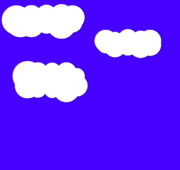
The silhouttes of the clouds appear a bit blurred in the above image, but this is simply a resizing artefact. The true output image is sharp.
To view it in your own Playground, make sure the Assistant Editor is open. Select Show Assitant Editor from the View menu.
Scenario 2: Generating Jigsaw Puzzle Pieces
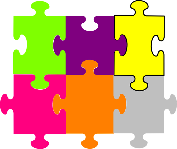
Jigsaw puzzle pieces usually have a square “frame”, with each edge being either flat, having a rounded tab protruding outwards, or a slot of the same shape to tesellate with a tab from an adjacent piece. Here’s a section of a typical jigsaw puzzle.
Accomodating Variations With Vector Graphics
If you were developing a jigsaw puzzle app, you’d want to use a puzzle piece-shaped mask to segment the image representing the puzzle. You could go for pregenerated raster masks that you shipped with the app, but you’d need to include several variations to accomodate all possible shape variations of the four edges.
With vector graphics, you can generate the mask for any kind of piece on the fly. Plus, it would be easier to accomodate other variations, such as if you wanted rectangular or oblique pieces (instead of square pieces).
Designing the Jigsaw Piece Boundary
How do we actually design the puzzle piece, which is to say, how do we figure out how to place our control points to generate a bezier path that looks like the curved tab?
Recall the useful tangency property of cubic Beziers I mentioned earlier. You can begin by drawing an approximation to the desired shape, breaking it up into segments by estimating how many cubic segments you’ll need (knowing the kinds of shapes a single cubic segment can accomodate) and then drawing tangents to these segments to figure out where you might place your control points. Here’s a diagram explaining what I’m talking about.
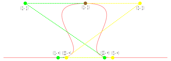
Relating the Shape to the Bezier Curve Control Points
I determined that to represent the tab shape, four Bezier segments would do nicely:
- two representing the straight line segments at either end of the shape
- two representing the S-shaped segments representing the tab at the center
Notice the green and yellow dashed line segments acting as tangents to the S-shaped segments, which helped me estimate where to place the control points. Note also that I visualized the piece as having a length of one unit, which is why all the coordinates are fractions of one. I could easily have made my curve to be, say, 100 points long (scaling the control points by a factor of 100). The resolution independence of vector graphics means this is a non-issue.
Lastly, I used cubic Beziers even for the straight line segments purely for convenience, so that the code could be written more concisely and uniformly.
I skipped drawing the control points of the straight segments in the diagram to avoid clutter. Of course, a cubic Bezier representing a line simply has the end points and control points all lying along the line itself.
The fact that you’re developing this in a playground means that you can easily “rejig” the control point values to find a shape that pleases you and get instant feedback.
Getting Started
Let’s get started. You can use the same playground as before by adding a new page to it. Choose New > Playground Page from the File menu or create a new playground if you prefer.
Replace any code on the new page with the following:
import UIKit

let outie_coords: [(x: CGFloat, y: CGFloat)] = [(1.0/9, 0), (2.0/9, 0), (1.0/3, 0), (37.0/60, 0), (1.0/6, 1.0/3), (1.0/2, 1.0/3), (5.0/6, 1.0/3), (23.0/60, 0), (2.0/3, 0), (7.0/9, 0), (8.0/9, 0), (1.0, 0)]

let size: CGFloat = 100
let outie_points = outie_coords.map { CGPointApplyAffineTransform(CGPointMake($0.x, $0.y), CGAffineTransformMakeScale(size, size)) }


let path = UIBezierPath()
path.moveToPoint(CGPointZero)

for i in 0.stride(through: outie_points.count - 3, by: 3) {
    path.addCurveToPoint(outie_points[i+2], controlPoint1: outie_points[i], controlPoint2: outie_points[i+1])
}

path
Generating All Four Sides Using Geometric Transforms
Note that we decided to make our path 100 points long by applying a scaling transform to the points.
We see the following result using the “Quick Look” feature:
So far, so good. How do we generate four sides of the jigsaw piece? The answer is (as you can guess), using geometric transformations. By applying a 90 degrees rotation followed by an appropriate translation to path above, we can easily generate the rest of the sides.
Caveat: A Problem With Interior Filling
There’s a caveat here, unfortunately. The transformation won’t automatically join individual segments together. Even though our jigsaw piece’s silhouette looks fine, its interior won’t be filled and we’ll face problems using it as a mask. We can observe this in the playground. Add the following code:
let transform = CGAffineTransformTranslate(CGAffineTransformMakeRotation(CGFloat(-M_PI/2)), 0, size)

let temppath = path.copy() as! UIBezierPath

let foursided = UIBezierPath()
for i in 0...3 {
temppath.applyTransform(transform)
foursided.appendPath(temppath)

}

foursided
Quick Look shows us the following:
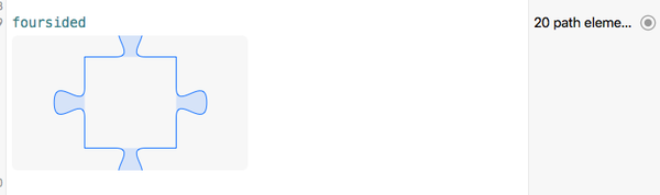
Notice how the interior of the piece isn’t shaded, indicating it hasn’t been filled.
You can find out the drawing commands used to construct a complex UIBezierPath by examining its debugDescription property in the playground.
Resolving the Filling Problem
Geometric transforms on UIBezierPath work quite well for the common use case, that is, when you’ve already got a closed shape or the shape you’re transforming is intrinsically open, and you want to generate geometrically transformed versions of them. Our use case is different. The path acts as a subpath in a larger shape that we’re building and whose interior we intend to fill. This is a bit trickier.
One approach would be to mess with the internals of the path (using the CGPathApply() function from the Core Graphics API) and manually join the segments together to end up with a single, closed and properly-filled shape.
But that option feels a bit hackish and that’s why I opted for a different approach. We apply the geometric transforms to the points themselves first, via the CGPointApplyAffineTransform() function, applying the exact same transform we attempted to use a moment ago. We then use the transformed points to create the subpath, that is appended to the overall shape. At the end of the tutorial, we’ll see an example where we can correctly apply a geometric transform to the Bezier path.
Generating the Piece Edge Variations
How do we generate the “innie” tab? We could apply a geometric transform again, with a negative scaling factor in the y-direction (inverting its shape), but I opted to do it manually by simply inverting the y-coordinates of the points in outie_points.
As for the flat-edged tab, while I could’ve simply used a straight line segment to represent it, in order to avoid having to specialize the code for distinct cases, I simply set the y-coordinate of each point in outie_points to zero. This gives us:
let innie_points = outie_points.map { CGPointMake($0.x, -$0.y) }
let flat_points = outie_points.map { CGPointMake($0.x, 0) }
As an exercise, you might generate Bezier curves out of these edges and view them using Quick Look.
You now know enough for me to blitz you with the entire code, which ties everything together in a single function.
Replace all the content of the playground page with the following:
import UIKit
import XCPlayground
enum Edge {
case Outie
case Innie
case Flat
}
func jigsawPieceMaker(size size: CGFloat, edges: [Edge]) -> UIBezierPath {
func incrementalPathBuilder(firstPoint: CGPoint) -> ([CGPoint]) -> UIBezierPath {
let path = UIBezierPath()
path.moveToPoint(firstPoint)
return {
points in
assert(points.count % 3 == 0)
for i in 0.stride(through: points.count - 3, by: 3) {
path.addCurveToPoint(points[i+2], controlPoint1: points[i], controlPoint2: points[i+1])
}
return path
}
}
let outie_coords: [(x: CGFloat, y: CGFloat)] = [/*(0, 0), */ (1.0/9, 0), (2.0/9, 0), (1.0/3, 0), (37.0/60, 0), (1.0/6, 1.0/3), (1.0/2, 1.0/3), (5.0/6, 1.0/3), (23.0/60, 0), (2.0/3, 0), (7.0/9, 0), (8.0/9, 0), (1.0, 0)]
let outie_points = outie_coords.map { CGPointApplyAffineTransform(CGPointMake($0.x, $0.y), CGAffineTransformMakeScale(size, size)) }
let innie_points = outie_points.map { CGPointMake($0.x, -$0.y) }
let flat_points = outie_points.map { CGPointMake($0.x, 0) }
var shapeDict: [Edge: [CGPoint]] = [.Outie: outie_points, .Innie: innie_points, .Flat: flat_points]
let transform = CGAffineTransformTranslate(CGAffineTransformMakeRotation(CGFloat(-M_PI/2)), 0, size)
let path_builder = incrementalPathBuilder(CGPointZero)
var path: UIBezierPath!
for edge in edges {
path = path_builder(shapeDict[edge]!)
for (e, pts) in shapeDict {
let tr_pts = pts.map { CGPointApplyAffineTransform($0, transform) }
shapeDict[e] = tr_pts
}
}
path.closePath()
return path
}
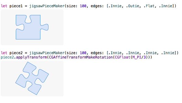
let piece1 = jigsawPieceMaker(size: 100, edges: [.Innie, .Outie, .Flat, .Innie])
let piece2 = jigsawPieceMaker(size: 100, edges: [.Innie, .Innie, .Innie, .Innie])
piece2.applyTransform(CGAffineTransformMakeRotation(CGFloat(M_PI/3)))
There are only a few more interesting things in the code that I’d like to clarify:
- We use an
enumto define the different edge shapes. We store the points in a dictionary that uses the enumeration values as keys. - We piece together the subpaths (consisting of each edge of the four-sided jigsaw piece shape) in the
incrementalPathBuilder(_)function, defined internally to thejigsawPieceMaker(size:edges:)function. - Now that the jigsaw piece is filled properly, as we can see in the Quick Look output, we can safely use the
applyTransform(_:)method to apply a geometric transform to the shape. As an example, I’ve applied a 60 degrees rotation to the second piece.
Conclusion
I hope to have convinced you that the ability to programmatically generate vector graphics can be a useful skill to have in your arsenal. Hopefully, you’ll be inspired to think of (and code up) other interesting applications for vector graphics that you can incorporate in your own apps.

Comments